Ultra Low Distortion Composite amplifiers based on LM1875
LM1875 is a little nice chip amp capable of providing 25W output power. If properly implemented it provides surprisingly good sound. The simplicity of the circuit and its sound quality have ranked that IC chip among the most popular among DIY enthusiasts.
When implemented according to data sheet the THD of the LM1875 power amplifier vs. output power shows a peak at about 0.5 watt (0.05% THD into an 8-ohm load and 0.1% THD into a 4-ohm load). The THD drops with increasing the output power and reaches its minimum of 0.02% at around 10W into 8 ohm. That pattern of THD vs. output power is caused by the thermal feedback on the IC chip (the output stage released heat changes the temperature of the input stage). Inserting the first stage of the composite leads to thermal decoupling of the input stage within a feedback loop from the output stage. This is the second benefit of our composite design. (The first benefit being the increased loop gain of the composite amplifier and significantly decreased THD, noise and output DC offset).
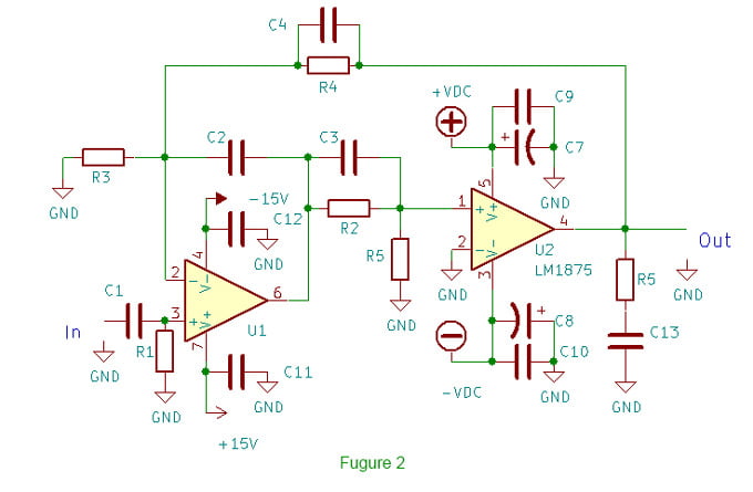
Figure 2 below shows the principal circuit of a non-inverting composite amplifier based on LM1875. The gain is 11 but any value between 5 and 20 works fine as well. Changing the gain however should be reflected in phase correction techniques.
LM1875 based composite amplifier circuit
The first thing that would strike anyone familiar with LM1875 is the lack of the feedback DC decoupling capacitor. The absence of the capacitor in the feedback greatly improves the sound of the composite. So this is the third benefit of the composite implementation – no need for feedback DC decoupling capacitor. Many would say “What about the output DC offset?”. Here is the answer – using a “proper” hi-performance op amp ensures DC offset at the output in the range of 0.2-2 mV in a wide temperature interval. If somebody can’t live with such a DC offset, using a servo is an option, but I personally couldn’t even make myself try servo in this case.
The input impedance of the amp is determined by R1, which in this case is 5.1K and a good compromise. If your pre-amp is capable of driving low impedance loads R1 could be decreased, which would benefit the op amp performance but prompts an increase of the capacitance of C1.
C2, C3, C4, R2, R3 and R4 shape the phase correction and gain of the composite (which are tightly connected) and precisely tune the op amp behavior as well. I have mentioned “proper hi-performance op amp” a few times and that is not a coincidence. The choice of the op amp is what makes the composite to work right. Unfortunately simulations won’t help much. There are at least 100 op amps from different manufacturers that look suitable for the purpose, but just a few of them really work as intended. Open loop gain, bandwidth, slew rate, distortion, noise, DC offset, etc, etc. All these parameters matter.
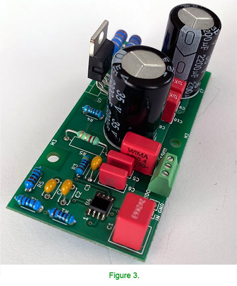
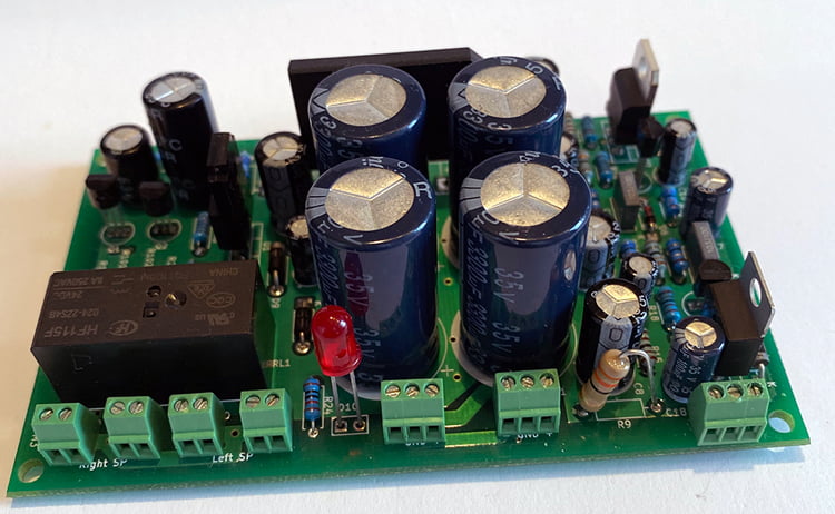
A practical implementation of the composite circuit discussed above is shown on Figure 3.
LM1875 composite amplifier board
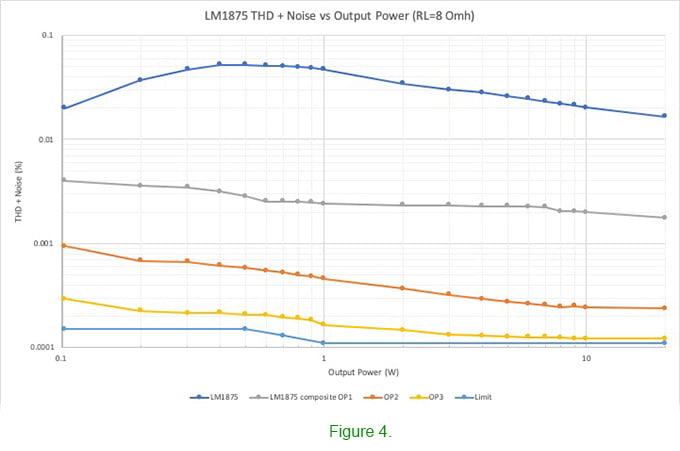
Total harmonic distortion (THD) is widely accepted as a physical measure of the sound quality of an amplifier. It is the total root mean square (rms) harmonic voltage in a signal, as a percentage of the voltage at the fundamental frequency. Nowadays however THD is often expressed in dB as well. THD should be as low as possible. Figure 4 shows the THD plots at 1kHz of a LM1875 based composite amplifier using three different operational amplifiers. For comparison the THD figure of the basic implementation of LM1875 is shown as well.
LM1875 based composite amplifier THD+noise vs output power
It’s easy to notice that the performance of the LM1875 amplifier is greatly improved. As was mentioned before, the operational amplifier plays a crucial role. Figure 4 demonstrates the performance of the composite amplifier with 3 different op amps – Op Amp1, Op Amp2 and Op Amp3. Op Amp1 and Op Amp2 have a similar bandwidth and slew rate, but Op Amp1 has a higher noise and Op Amp2 has roughly 25dB higher open loop gain. Op Amp 3 is a super high performance operational amplifier. The phase correction in each case was tailored according to the characteristics of each op amp.
Out of curiosity I tried a composite amplifier (equipped with Op Amp3) at unity gain. It is possible to achieve a stable working amp but in expense of very high common mode distortion. The inverting configuration avoids that problem but has other faults. The best results (high stability and low distortions) I got at gain between 5 and 15.
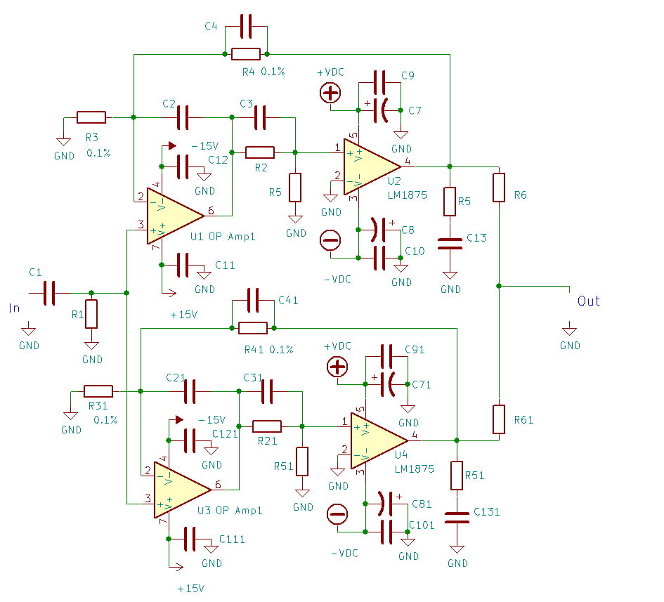
Paralleling two or more composite amplifiers benefits the performance (more power, less THD and noise) but there are some important requirements that should be kept in mind when doing that. The most important ones are: very low DC offset at the output, equal (as close as possible) gain, equal LM1875 cooling conditions. The first of these is already achieved (DC offset being around 1mv). The second is achievable by using matched NFB resistors, or using resistors with tolerance less than 0.1%. Fig. 5 shows the principal circuit of two composite amplifiers working in parallel.
Two LM1875 based composite amplifiers in parallel
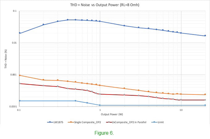
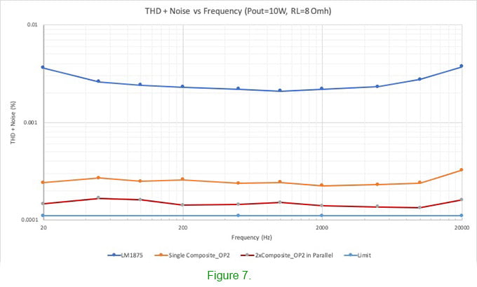
The effect of paralleling is shown on Figures 6 and 7 – THD and noise are reduced roughly by factor of 1.5.
LM1875 composite amplifier parallel THD vs output power.
LM1875 composite amplifier single parallel THD vs frequency
Power supply requirements
To achieve high performance and good sound, the composite amp (and any other amp) should be fed by an adequate power supply. For all the tests I used regulated ±28.5V Switching Power Supply able to deliver approximately 15A continuous current with 40mVp-p ripple. Note that the supply voltage must not exceed ±30V at any time – this is the absolute maximum voltage rating for the LM1875.
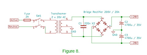
A conventional ±28.0V PSU is shown on Figure 8. The transformer may be E-I type or a toroid. The latter has the advantage of lower leakage flux, so will inject less noise into the chassis and wiring, which is important if you aim at lowest possible noise. A 70-80VA transformer is enough for 2x25W output power.
Power supply plus minus 28V
The op amp PSU is more important. High PSRR (and low noise if possible) is a must. The data in the table bellow summarizes the effect of the Op Amp PSU (±15.0V) on THD+noise performance of the composite amp based on OP Amp3 @ 1W output power (RL=8ohm) @ 1kHz:
Table 1. Effect of the operational amplifier power supply on the THD+noise
PSU THD+noise
Zener diodes -90dB (0.003%)
LM317/337 Reg. -106dB (0.0005%)
Improved LM317/337 Reg. -116dB (0.00015%)
Low noise / Low Ripple Reg. -120dB (0.0001%)
The increase of THD+noise is mainly due to the increased noise level at low frequency while THD level is not affected so drastically.
Figure 9 shows a PSU suitable for low noise, low THD composite amplifier. The PSU is combined with speaker DC protection and delay circuit. The low voltage unit (±15.0V) has very low noise (less than 5uV) and high PSSR (>85-90dB). It is able to provide 150mA of current and can be used to feed preamps or other equipment with very clean ±15.0V.
Low noise power supply and speaker DC protection and delay PCB
PCB Layout requirements and parts selection
As the described composite has an amplifier (LM1875) within its feedback loop, the differing frequency response poles of each amplifier could interact, causing circuit instability. Therefore, proper component layout and grounding are very important. Inadequate circuit grounding and layout can increase the noise and THD by an order of magnitude.
For a long time many audio enthusiasts embraced the idea that the extremely short feedback path is crucial for the sound quality of LM1875. The proper layout design is of course very important for the sound quality of LM1875 but the extremely short feedback path is not (according to all my measurements and blind tests). Sometimes the opposite might be true. In an attempt to shorten the feedback path as much as possible, the designer might overlook other important layout requirements which may result in degradation of the sound quality. Anyway, “an incredibly short feedback path length” requirement was not among the important design rules of the layout of the PCB shown on Fig. 2.
In the composite circuit described above I did not use any “exotic”, “audiophile grade” parts. All resistors are metal film resistors, 1% tolerance. Phase correction capacitors are ceramic NP0 type 50V. Electrolytic capacitors are low ESR type. The input DC blocking capacitor is either PP or PE. The operational amplifier needs to be high performance but I found just 4 or 5 out 98 to be suitable. Phase correction itself is not difficult but obtaining ultra linear (non distorted) output signal is.
Output Power
The LM1875 limits the power supply voltage excursion of minus about 2.5 volts on top and bottom at 15W (Rl=8 Ohm), 3.5 volts at 20W, etc. Theoretically the maximum voltage across the load with ±28.5V PSU is ±24Vp-p or 17.0V (rms) or 36W (Rl=8 Ohm). According to the data sheet, above ±20V output voltage the overload protection of LM1875 becomes active and limits the output current. The LM1875 not only limits current to around 4A, but also reduces the value of the limiting current when an output transistor has a high voltage across it. Limiting the output voltage to ±20Vp-p (14.1V rms) at 4A ensures 25W output power (Rl=8 Ohm). In this way there is no reason to use supply voltage above ±25V.
The above is true for the conventional LM1875 circuit but not for the composite implementation. The composite amp is able to provide almost ±22.5Vp-p undistorted (16V rms) output voltage or 32W output power (Rl=8 Ohm, ±28.5V PSU) before the current limiting system becomes active (and completely destroys the sound). It is almost a 30% of increase of the output power of LM1875 which is another benefit of composite circuit. Paralleling two composite amps increases the clean output power up to 42W (RL=8 Ohm).
High Power Version
For those in need of more power there is a solution as well. In this case two parallel composite amplifiers in BTL configuration would be able to provide easily 100W (Rl = 8 ohm) output power. Since in my main setup I use 4 way active speakers I did get involved too deeply in that direction but it is worth to mention that two parallel composite amplifiers in BTL configuration show THD + noise plots equal to the measuring floor and sound extremely well. To invert the input signal you need a simple pre-amp similar to that shown on TDA7293 composite circuit.
How does it sound, or what is it all about?
After many, many hours of listening and numerous blind tests there is no doubt about the huge advantage of the composite amplifier over all conventional LM1875 circuits which I know (non inverting, non inverting + servo, inverting, LM1875 implementation with super short feedback length). The most common thing which people say during the blind tests is “Hey, who pulled back the curtain?” when switching from conventional to composite amp. The sound is open and transparent, with a detailed soundstage.
A few words about the correlation between THD+noise level and sound quality. As Figure 4 shows, using different op amps results in different THD plots. The blind tests between composite amps featuring different op amps and LM1875 basic implementation clearly demonstrated that the lower THD level corresponds to better sound quality but that correlation is not quite simple. The difference of the sound quality between LM1875 (blue line on Figure 4) and the composite exhibiting the grey line is very clear and anyone was able to hear it (12 out of 12). The difference between the composites represented by the grey and red lines is very clear as well, almost anyone (10 out of 12) distinguishes the later as better. When it comes to the composites represented by the red and yellow line almost half of the participants (5 out of 12) couldn’t distinguish which one they like more. So if you are among those 58% able to make the distinction then it is worth spending a few bucks more and have the best.
All tests were carried out on 4-way active open baffles.