SMPS in high quality audio power amplifiers
For many, if not all, high quality audio lovers the title sounds like an oxymoron, i.e. SMPS and high quality sound are incompatible, they can’t live together. Quite often the sound produced by amplifiers equipped with SMPS is characterized as weak, lack of bass performance, unpleasantly noisy, etc. and in most of the cases it is not just an imagination or prejudices, it is the reality. That reality is kind of disappointing since the switching mode power supplies have a lot to offer – regulated output, overload and temperature protection, low cost, high efficiency.
The aforementioned disadvantages are mainly associated with the inability of the most SMPS to handle high capacitive loads, the HF noise which they insert into the output DC voltage and the strong electromagnetic and switching noise in their vicinity.
The electromagnetic and switching noise are in close relation to the design and once produced are very difficult to get rid of them. Fortunately, most of the SMPS manufactured nowadays comply with the EMI regulations.
The high quality audio reproduction (especially LF spectrum) is directly connected to the amount of the reservoir capacitors in the power supply. Those capacitors are vital, ensuring low ripple, supplying enough current when it is needed, etc. It is not an unusual advertising strategy to praise the quality of a power amplifier mentioning the amount of the reservoir capacitors – 2×50,000uF, 2×75,000uF etc. Of course that approach (increasing the amount of the reservoir caps) has its boundaries beyond which it does no bring any further improvement. The task of the designer is to find those boundaries for any particular design.
Getting back to the SMPS. Is there a way to increase the capacitance load of a SPMS, let’s say to 20,000uF, but not confronting its stability. Yes! It is possible but the circuit will become unnecessarily complicated and definitely not cheap. So, what else can be done. There is a very simple solution which is to introduce a buffer stage between the SMPS output and reservoir capacitors, preventing the output to “see” directly the capacitance load. Well, that buffer might be very well known capacitance multiplier. There are some tradeoffs, of course, but they are quite minor, I would say. What are they: first – introducing an additional circuit, second – the need to dissipate the heat released by the transistor, third – loss of the regulation. How bad are these tradeoffs?
The circuit is very simple and consists of only 6 parts. How does it handle the heat dissipated by the transistor? Actually it is not much. For example, an amp capable of producing 60W (RMS) @ 8 Ohm would require the capacitance multiplier transistor to dissipate heat equivalent to approximately 3.5W. So a heatsink with a thermal resistance of 5—6 K/W would be enough to keep the temperature of that transistor in very reasonable boundaries. How about the loss of the regulation? In the same example the fluctuation of the output voltage is less than 0.5V, which I think is perfectly fine.
There is another benefit of inserting the capacitance multiplier between the output of the SMPS and load – significantly reducing the switching noise and completely eliminating the output ripple.
A practical implementation of the above is illustrated on Fig. 1 and fFg. 2.
Fig. 1. Capacitance multiplier circuit.
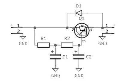
R1=R2=100 Ohm, C1=C2=1800uF, D1 – 1N4001, Q1 – TIP142
Fig. 2. A SMPS followed by capacitance multiplier.
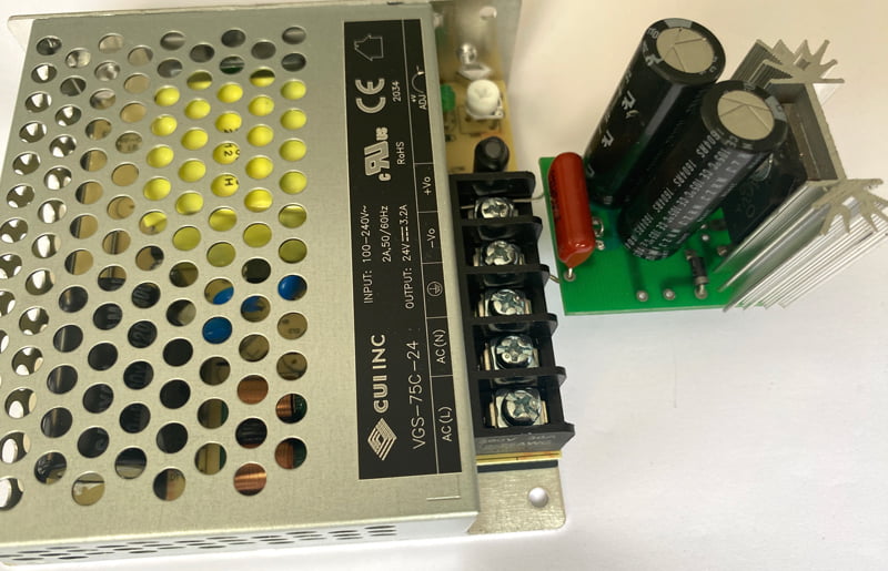
For the negative rail the polarity of the electrolytic capacitors should be inverted, the protection diode should be reversed as well and the transistor should be TIP147.
The Darlington transistor could be easily substituted by two regular BJT – BD139+TIP35 for TIP142 and BD140+TIP36 for TIP147. Capacitors should be in the range of 470uF – 1800uF, in this case the bigger is better.
Summing up:
Inserting a simple circuit at the output of an inexpensive SMPS allows us to increase the capacitance load up to 20,000uF or more. I tested the setup up to 33,000uF and it worked perfectly well. Reducing the output noise and ripple to ~5.0mV RMS (24V, 3.5A load).
So for around $35-40 you can get a couple of SMPS ($13 each) and all the parts for the capacitance multipliers and build an excellent power supply capable of driving, for example, 2x60W (@4 Ohm) amplifier. On top of that you have the freedom to adjust the output voltage from +/-21.5V to +/-28.0V (or +/-31.0 to +/-39.0V (if you get a different SMPS model), short circuit / over load / over voltage protection, +/-0.5V output voltage fluctuation, very low noise level and almost no ripple.
Wiring
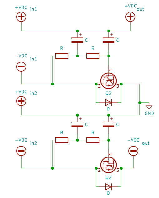
There are four ways to wire the SMPSs and capacitance multipliers. They are shown on Fig. 3, Fig. 4, Fig. 5, and Fig. 6.
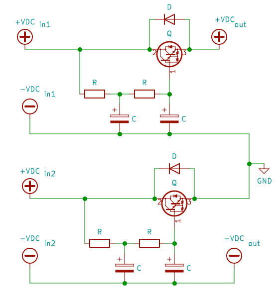
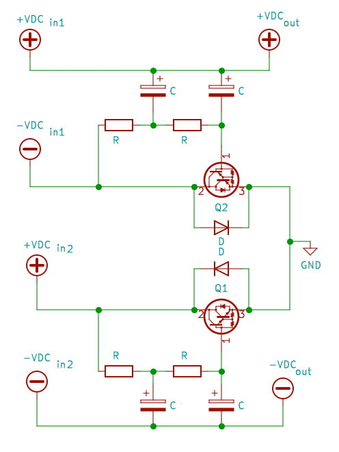
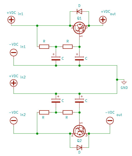
+VDCin1 and -VDCin1 are connected to the positive and negative outputs of SMPS1. +VDCin2 and -VDCin2 are connected to the positive and negative outputs of SMPS2. Q1 – TIP142, Q2 – TIP147.
How do the different wirings perform in terms of output noise and ripple? Theoretically they should perform identically. But actually they don’t. The wirings shown on Fig. 3 and 4 perform almost identically. The wiring shown on Fig.5. has the lowest noise and ripple and the wiring shown on the Fig. 6 is worse than that on Fig. 5 but better than those on Fig. 3 and 4. Are these differences important for the performance of the power amp. Absolutely not! So which one to choose? I would stick to the last one.