Ultra-low noise and distortion preamplifier with balanced and unbalanced inputs
The preamplifier presented bellow is an attempt to provide DIY audiophile enthusiasts with a versatile solution suitable for any active speakers or power amplifiers input stage. The specs and the quality of the sound will probably satisfy the most if not all DIY audiophile enthusiasts.
The preamp features balanced and unbalanced inputs, low impedance output, capable of driving low impedance loads (650Ohm or more) and subsonic signals free low impedance output as well. The architecture and the use of high quality op amps ensure the ultra-low distortion and noise performance.
First some basic theory, but for those who are more interested in the circuit it is shown on fig. 1.
Signal Levels and Dynamic Range
The signal level should be considered very carefully as it determines the signal to noise ratio and the headroom. If the signal level is too low, it will be susceptible to noise contamination. The absolute level of noise in a circuit is not of great significance in itself — what counts is how much greater the signal is than the noise — in other words the signal to noise ratio. On the other hand if the signal level is too high there is a risk of clipping, severe distortion and speakers damage.
The wider the gap between the noise floor and the clipping level, the greater is the dynamic range. When the best possible signal-to-noise is required for audiophile applications, then the internal level should be as high as possible, and if there is an unexpected mild overload it’s not the end of the world.
The levels in the signal path are measured in dBu, as 0 dBu is 775 mV RMS. Here are some often mentioned signal levels: –16 dBu is 123 mV RMS, −6 dBu is 388 mV RMS, −2 dB is 615 mV RMS, +2 dBu is 0.975 mV RMS, +6 dBu is 1.546 V RMS and +22 dBu is 10 V RMS.
The best way to maximize the dynamic range is to lower the noise floor as much as possible. The noise floor is determined mainly be Johnson noise and the voltage noise, and the current noise of the active devices (op amps). Minimizing the noise floor can be done by using ultra-low noise op amps (minimizing the voltage and current noise) and adopting the low impedance approach (minimizing both, Johnson noise and current noise). Low impedance approach means using the lowest possible resistor values. For example decreasing a resistor value from 10k to 1k increases the dynamic range by at least 10dB, which is very good, of course, but op amp distortion will start to increase due to the heavier loading. To prevent this to happen one should consider using ultra-low distortion op amps.
Summing up: To obtain an excellent dynamic range one should adopt low impedance approach and implement it by using ultra-low noise and distortion op amps.
External Signal Levels There are adopted standards in professional audio equipment for line signal levels but in nonprofessional audio equipment such standards simply don’t exist as different manufacturers follow their own standards. In general the the external signal levels can vary from −6 dBu (388 mV RMS) to +8 dBu (1.95 V RMS). Nowadays a huge number of the audio devices, such as DACs, rely on 5V USB power supply so usually their output signal is limited to 2Vp-p (700 mV RMS, -0.88dBu) or even lower.
Input Amplifier Functions
1.RF filtering. It is vital that the first thing which an incoming signal meets is some form of RF filtering, to prevent RF breakthrough and other EMC problems. It must be done before the incoming signal encounters any semiconductors where RF demodulation could occur. If it happens there is no way to get rid of the parasitic signals.
2. DC-blocking. The low-end frequency response is established by DC-blocking capacitors and input resistors. An input amplifier should have a reasonably high impedance; certainly not less than 10 kΩ, and preferably more.
3. Appropriate gain. It must have a suitable gain to scale the incoming signal to the nominal internal level.
4. Signal conversion. Balanced input amplifiers subtract and convert the differential signals to single-ended ones, so noise produced by ground loops and the like is rejected.
Unbalanced and balanced inputs
The unbalanced input serves as a buffer between the incoming signal and the next stage and at the same time ensures the functionalities mentioned above. In addition to those functions, there is one more which is very important – impedance matching. Quite often the following stage requires a low source impedance to give the expected response (active filters for example) and at the same time its own input impedance may vary with frequency and could fall to rather low values. Balanced inputs are used to prevent the input signal from noise and crosstalk, usually generated where long interconnections are used. They are standard on professional audio equipment, and are gaining popularity in the world of hi-fi. Their significance is that they can render ground loops and other connection imperfections harmless. Since there is no point in making a superb amplifier and then feeding it with an impaired signal, the designer should consider the necessity of an effective balanced input as of the first importance.
The Advantages of Balanced Connections
• Balanced connections eliminate the noise and crosstalk, whether they result from ground currents, or electrostatic or magnetic coupling to signal conductors.
• Balanced connections make ground-loops almost invisible (inaudible)
• Balanced connections provide 6 dB signal boost, potentially giving 6 dB more dynamic range.
It is very important to keep in mind that all these advantages heavily rely on CMRR of the balanced input. A balanced input with excellent specs but poor CMRR will render itself useless.
Disadvantages of Balanced Interconnections
• Balanced inputs are inherently noisier than unbalanced inputs by a large margin, in terms of the noise generated by the input circuitry itself rather than external noise. This may appear paradoxical but it is the reality.
• Balanced inputs and balanced connectors are more expensive.
• Balanced connections do not provide better RF immunity than an unbalanced input. It remains vital to provide the passive RF filtering before the first active elements.
Unbalanced and Balanced Signal
Levels If a piece of equipment has both, unbalanced and balanced outputs and the unbalanced output is, lets say, 0.5 Vrms, then it translates into 1 Vrms total balanced output (the voltage between hot and cold pins), and so the balanced input must have a gain of 1⁄2 or −6 dB relative to the unbalanced input to maintain consistent internal signal levels.
Subsonic and Ultrasonic Filters
Subsonic filters are high-pass filters used to stop subsonic signals and so protect power amplifiers and loudspeakers from damage. They might be placed as early in the signal path as possible, immediately after the input stage to prevent headroom being eroded by large subsonic signals or as a first stage in the LF path, assuming that the high-pass filters in the HF and MID paths will remove the subsonic signals very effectively. Usually a third-order Butterworth filter (18 dB/octave) with a cutoff frequency around 20Hz is the best approach. In this way the HF and MID signals won’t be altered/degraded by subsonic filter.
Ultrasonic filters are also intended for speaker protection, in the event of HF instability/oscillation somewhere in the audio system. A typical ultrasonic filter would be a second-order Butterworth with a cutoff frequency around 40 – 50 kHz. The ultrasonic filter should be placed in the HF crossover path, as the lowpass filters in the LF and MID paths will very effectively remove any ultrasonic signals.
The combination of a subsonic filter and an ultrasonic filter is sometimes used (so called a bandwidth definition filter) but the better option is to use separate filters in different places in the signal path.
Fig.1 shows the preamp circuit.
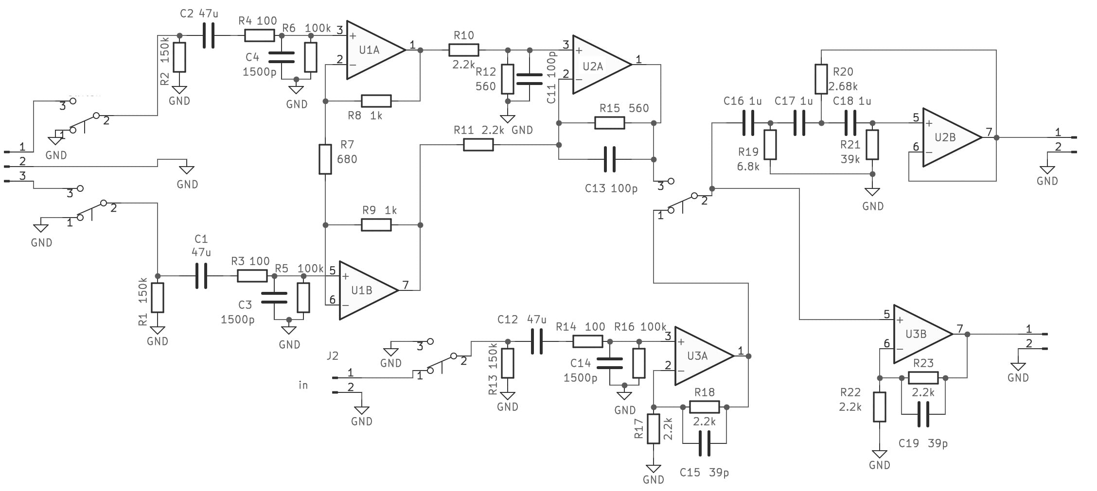
The balanced input is build around well known instrumentation amplifier. The total gain of the balanced input is G = 1 (0dB). The advantages of such architecture over the conventional one are: better noise performance (around 5 dB lower noise floor), better CMRR (12dB improvement), high input impedance. The disadvantage is the higher cost.
R3, C3 and R4, C4 serve as RF filters, C1 and C2 – DC blocking.
The unbalanced input gain is set to G = 2 and has the same RF filtering and DC blocking as the balanced input. The switching between balanced and unbalanced input is accomplished by 4PDT switch.
The signal of output 1 is subsonically filtered – cutoff frequency 19Hz and roll of 18 dB/oct. This output should be routed to LF section of active speakers.
The output 2 has gain set to G = 2 can be used as a signal source for any power amplifier or can be routed to HF and MID sections of active speakers. If different gain is needed R22 should be adjusted accordingly.
specs:
Frequency response – 20Hz – 20kHz (+/- 0.2dB), 25Hz-20kHz Subsonic filter (+/-0.2 dB)
Input impedance – 60K
THD + noise < -119dB (+6dBu)
Max input voltage – 2.5V RMS (+10.0 dBu)
Power supply – +/-15V (low ripple, low noise)
An assembled PCB of the preamp is available in the store section.